Port usage overview
| Port |
Description |
| PTA1:6 |
Keyboard columns (see below sections) |
| PB |
Keyboard (see below sections) |
| PTD5 |
slim
backlight (1=ON) |
| PTE0 |
SD-option flag (1=present); not with the GII |
| PTE1 |
RAM-size flag (1=512 k; 0=256 k) |
| PTE3 |
model
flag (1=standard; 0=slim) |
| PTG6:5 |
enable
serial interface (1=enabled) |
| PTG7 |
GII
backlight (1=ON) |
| PTH1 |
power
good signal on models without backup battery |
| PM |
Keyboard (see below sections) |
|
PTL1:2/"AN1:2" |
Battery level detection (see sections below) |
On the GII the SD-option is coded in the byte at 0xA0000304. It is equal to
0xFF with the SD type.
The GII is detected by *(int*)0xA5603A98==1.
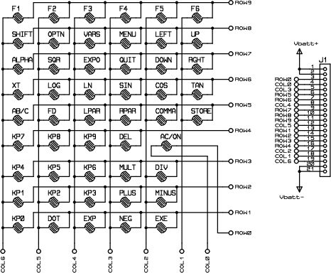
Keyboard PCB
This shows all connections from the key and main battery
board, to the ribbon cable. Pin 1 of the ribbon cable is the one near "JN101"
on main PCB.

Port A (columns)
COL6:0 => PTA6:0
Port M (remaining upper rows)
ROW11 -> ? (used for the 'pad
connectors' on the PCB)
ROW10 -> ? (used for the 'pad connectors' on the PCB)
ROW9 -> PTM1
ROW8 -> PTM0
Port B (lower 8 rows)
ROW7:0
=> PTB7:0
The following code
demonstrates the way to check a single row, which is the input parameter of
CheckKeyRow.
CheckKeyRow returns the pressed-key-mask of the checked row.
As mentioned above, Port A is the detector. Port B and port M are the injector
ports.
void delay(
void ){
int i;
for (i=0;i<5;i++){};
}
//
int CheckKeyRow(
int row ){
int result=0;
short*PORTB_CTRL=(void*)0xA4000102;
short*PORTM_CTRL=(void*)0xA4000118;
char*PORTB=(void*)0xA4000122;
char*PORTM=(void*)0xA4000138;
char*PORTA=(void*)0xA4000120;
short smask;
char cmask;
smask = 0x0003 << ((row%8)*2);
cmask = ~( 1 <<
(row%8)
);
if (row<8){
// configure port B as input, except for the "row to
check"-bit, which has to be an output.
*PORTB_CTRL =
0xAAAA ^ smask;
// configure port M as input; port M is inactive with row
< 8
*PORTM_CTRL = (*PORTM_CTRL
& 0xFF00 ) |
0x00AA;
delay();
*PORTB = cmask;
// set the "row to check"-bit to 0 on port B
*PORTM = (*PORTM
& 0xF0 ) |
0x0F; // port M
is inactive with row < 8
}else{
*PORTB_CTRL =
0xAAAA; // configure port B as input; port B
is inactive with row >= 8
// configure port M as input, except for the "row to
check"-bit, which has to be an output.
*PORTM_CTRL = ((*PORTM_CTRL
& 0xFF00 ) |
0x00AA) ^ smask;
delay();
*PORTB = 0xFF;
// port B is inactive with row >= 8 (all to 1)
*PORTM = (*PORTM
& 0xF0 ) | cmask;
// set the "row to check"-bit to 0
};
delay();
result = ~(*PORTA);
// a pressed key in the row-to-check draws the
corresponding bit to 0
delay();
*PORTB_CTRL = 0xAAAA;
*PORTM_CTRL = (*PORTM_CTRL &
0xFF00 ) | 0x00AA;
delay();
*PORTB_CTRL = 0x5555;
*PORTM_CTRL = (*PORTM_CTRL &
0xFF00 ) | 0x0055;
delay();
return result;
}
#define KB_1ST_ROW 9
#define KB_2ND_ROW 8
#define KB_3RD_ROW 7
#define KB_4TH_ROW 6
#define KB_5TH_ROW 5
#define KB_6TH_ROW 4
#define KB_7TH_ROW 3
#define KB_8TH_ROW 2
#define KB_9TH_ROW 1
#define KB_0TH_ROW 0
#define KB_F1_ROW KB_1ST_ROW
#define KB_SHIFT_ROW KB_2ND_ROW
#define KB_ALPHA_ROW KB_3RD_ROW
#define KB_XTT_ROW KB_4TH_ROW
#define KB_ABC_ROW KB_5TH_ROW
#define KB_7_ROW KB_6TH_ROW
#define KB_4_ROW KB_7TH_ROW
#define KB_1_ROW KB_8TH_ROW
#define KB_0_ROW KB_9TH_ROW
#define KB_AC_ROW KB_0TH_ROW
#define KB_1ST_COL 0x40
#define KB_2ND_COL 0x20
#define KB_3RD_COL 0x10
#define KB_4TH_COL 0x08
#define KB_5TH_COL 0x04
#define KB_6TH_COL 0x02
#define KB_7TH_COL 0x01
#define KB_AC_COL KB_7TH_COL
#define KB_ALPHA_COL KB_1ST_COL
#define KB_SQUARE_COL KB_2ND_COL
#define KB_POW_COL KB_3RD_COL
#define KB_EXIT_COL KB_4TH_COL
#define KB_DOWN_COL KB_5TH_COL
#define KB_RIGHT_COL KB_6TH_COL
Battery level detector
ADC functionality of Port
L is used to measure battery voltage level.
Main batteries: PTL2/AN2
(Possibly also: Backup battery(?): PTL1/AN1 (3V) )
(16.10.2011 09:20:37)

